Sunday, November 15, 2009

21. MODEL RAILROAD TOUR


NOV 15, 2009

21 Model Railroad Tour

Friday November 13 and Saturday November 14 was the First Annual Southern Utah Model Railroad Tour sponsored by the Southern Utah Division, Rocky Mountain Region of the National Model Railroad Association sponsored by the Color Country Model Railroad Club. The goal was to have trains running on the Ascape Tennsion & Sulphur Gulch Railroad by this date. Thanks to members of the model railroad club who were involved in to a couple of work Saturdays and a late work night Thursday November 12 the goal was met and the first trains ran Friday Night. Particular thanks to Doug Whetstone who coordinated these work activities and spent many hours personally getting the ATSGRR ready to run. Without this effort by Doug and members of the club the trains would still be residing in their storage boxes where they have resided since 2004.

Friday morning, after 5 years in storage, boxes were opened and some of the rolling stock and the locomotives of the the ATSGRR arrived on the newly laid track. The management was most pleased with the result when the trains ran from Ascape to Echo Junction without any problems. There were still track problems in the helix so there was no traffic from staging.

Photo 1 shows a view of the Ascape yard with three trains ready to make the run from Ascape to Tennsion and then up the grade to Coalville and Echo Junction. In the upper left of the photo you cansee the other locomotives that operate on the AT&SG. You will note that the Ascape passing siding and station siding are in place but the yard tracks are not yet in place. The trains are sitting on the Ascape passing siding.

Photo 2 shows number 82, a 2-8-0 consolidation with a 10 car freight ready to tackle the grade. The locomotive was able to handle the grade but will obviously need a helper during operating sessions for trains longer than 8 cars. The photo also shows number 7, a three truck shay with a short string of log buggies ready to tackle the grade. You can see the track support for the high line at Echo Junction behind the locomotives.

Photo 3 shows number 9, a 2-6-6-2 Uinta sitting on the siding at Echo Junction with a string of loaded coal hoppers ready to descend the grade to Ascape for shipment on to Provo. It was able to negotiate the down hill grade with ease and was also able to the same loaded hoppers up the grade from Ascape to Echo Junction.

The visitors really seemed to enjoy the event. The little bit of scenery that was completed for the demonstration held earlier really helped them to visualize the finished railroad. A few structures were also placed in the approximate location on the layout. However most of the layout was more "roller coaster" in appearance with roadbed and track suspended in space. Running trains on this exposed roadbed caused some anxiety for the management but fortunately the only crash occurred when a train was pushed through a closed switch causing one box car to plunge to the depths.

The next big event is a New Year open house January 2, 2010. Hopefully natural events will cause mountains to rise, rivers to flow, trees to sprout, and structures to be erected before this event. One thing is for certain, the investors will be happy to know that trains began to run by the end of 2009 as specified in the contract with the land owner. Trains will for sure be running for the new year in 2010. The management hopes to see you at the open house. It is anticipated that regular operating sessions will commence early in 2010.

Thursday, October 15, 2009

20. SCENERY DEMONSTRATION


October 8 the HO group of the Color Country Model Railroad Club met at the Site of the Ascape Tennsion & Sulphur Gulch Railroad for a demonstration on how to create scenery using cheese cloth. Most members of the club have not seen this method of scenery construction in the past.

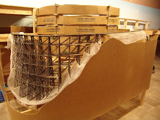
Prior to the demonstration the excavating team for the ATSGRR worked hard to construct the part of the mountain above Sulphur Gulch. The mountain was deliberately left in stages to show the whole process. The first photo shows this section of mountain.

For those with a technical interest the remainder of this post gives the blow-by-blow description of the construction process. The following are the steps in the process.

1. Before the construction of nature can begin complete the infrastructure for the surrounding area. On the ATSGRR this consisted of completing the trackbed for the high line at Echo Junction, the trackbed leading from Echo Junction to the top of the helix to return to staging, and the trackbed from Echo Junction across behind the helix to Park City which is located above the workbench roll-top desk on the other side of the helix. It was also necessary to complete the protective barrier around the outside of the helix to prevent trains from accidentally jumping to their destruction inside the mountain.

2. Place fascia around the edge of the layout in the area where the scenery is to be created. In the case of Sulphur Gulch this fascia is rather large with a contour cut to expose Sulphur Gulch and Trestle.

3. Place cardboard strips to create the contour of the mountain. They are held in place with hot glue and a couple of support posts inside the helix. The mountain forms a shell over the helix that is open in the middle so that someone can stand inside the helix when repairs are necessary or an accident occurs. The top of the mountain is above eye level so that spectators cannot view the inside of the helix even though the top of the mountain is open.

4. Stretch cheese cloth over the cardboard lattice work and hold it in place by white glue.

5. Paint a soupy mixture of plaster of Paris onto the cheese cloth forming a thin plaster shell when it dries. In places subject to strain or possible bumping from tourists paint several coats of plaster to form a more rigid shell.

6. Make plaster castings from rubber molds formed over real rocks. When the plaster in the mold is still damp but not yet set firm press the casting in place on the plaster shell. The castings can be forced into indentations in the shell to form small canyons as shown in the picture.

7. Add additional plaster to fill in spaces between castings and to form rocks where castings may not be appropriate or available. If molds for blasted rock are not available trawl a thick coat of plaster (2/8") over the plaster shell. While it is still damp carve this plaster by hand to resemble the rock from the molds or to form blasted rock faces where the mountain has been cut away to accommodate the track. At the damp stage the plaster will chip away in a most realistic fashion. Use an Xacto knife to cut horizontal seams in the rock face as occurs in nature. Randomly scratch and prick the rock face with a small piece of a wire brush to further deface the rock. With a little practice it is pretty easy to create realistic appearing rock cliffs.

8. After the rock castings are dry spray them with a mixture of wet water (water with a drop or two of detergent added) containing a few drops of India ink. This flows into the cracks and crevices of the rock to make them more apparent and to form shadows.

9. Using latex house paint representing the color of the soil in the area being modeled paint the shell in areas not covered by rock castings. Where the rock castings are in place spray a thinned (12:1) mixture of the soil colored paint and wet water onto the rocks. This thin paint runs a little forming natural looking variation in color.

10. Using earth colored pastel chalks dry brush various colors onto the rocks to form more variety in the color. Go easy as too much color does not look realistic. When the cliff looks like the real thing spray a dull coat matte finish over the work to keep the chalk from smearing.

11. Complete the scene by applying a coat of diluted white glue over the painted surface of the ground and sprinkling on fine ground foam (The ATSG uses Woodland Scenic Products) in appropriate colors for the area and season being modeled. Add shrubs from clump foam and plant trees as appropriate.

For more information about water based scenery consult

Dave Frary -- How to Build Realistic Model Railroad Scenery 3rd Edition

http://www.kalmbachstore.com/12216.htm

For more information about cheese cloth scenery consult

http://www.ucwrr.com/Kelly%27sScenery.htm

Sunday, July 26, 2009

19. CORK AND CHEESE CLOTH


Much of the spline roadbed is now installed on the ATSGRR. After the spline is in place the next step is to sand the top smooth. No matter how careful the track crew tries to be there is always one or two strands of the spline that insists on being a bit higher than the rest. A belt sander does the trick to smooth the top as seen in the photograph to the right.

Once the top is relatively smooth the next step is to install cork for
the ballast and to provide a smooth service for the track. The cork is secured to the spline with white or carpenters glue and help in place while the glue drives by a few staples from a staple gun. Driving spikes into the spline is a bit difficult but with the cork in place this is an easy task. For turnouts it is more convenient and provides a smoother surface for the turnout to use sheet cork that matches the ballest cork in height to cut pieces that underlie the turnouts.


The scenery for the railroad will be constructed on a web of cardboard stringers covered with cheese cloth. A later post will detail this process as it proceeds. But for now rather than attach the cheese cloth to the roadbed after the fact it is easier to lay a piece of cheese cloth on top of the spline and then lay the cork ballast strip on top of the cheese cloth. This way when the cardboard stringers are in place to form the mountains and valleys this cheese cloth forms a very smooth transition from the roadbed the the scenery. This prevents separation of the scenery from the roadbed which has occured in the past.

Once the cork in in place the track can be spiked in place on the cork ballest.

Sunday, June 7, 2009

18 STAGING TRACK


As soon as work resumed on the railroad the road gang went to work on laying track. As indicated in they previous diagrams the staging yard consists of a double ended yard with a ladder on either end. The longest track is more than 10 feet long, far longer than any train that will be able to make the 3% grade to climb the helix. The shortest track is about 3 feet long. The operation of the yard is to enter from the helix at the far end in the picture, proceed along the through track closest to the front of the yard (the left hand track in the picture) and then around the return loop at the end of the yard entering the ladder (shown in the picture) and being stored on one of the other six tracks in the yard ready for the next trip across the railroad. Since both ends of the railroad enter the helix this is true for both westbound and eastbound trains.

Details: If you have a causual interst in Model Railroads you may want to skip the following details which are primarily for those interested in construction techniques, materials used, etc.

Track: As indicated in an earlier post the track bed is homosote. The track is code 100 Atlas Flex track. This track is easy to use and is secured by means of a nail in about every 10th tie. The turnouts are a variety of brands rescued from the previous ATSG Railroad. They were salvaged when the railroad was disassembled. As a result the major construction task was to clean up the ends of the rails, repair sections which had come loose from their ties, and replace missing track. All the turnouts are #6 to facilitate the largest locomotive on the railroad (a Bachman Mountain 2-8-4).

An earlier railroad demonstrated the desirability of having a rerail section near the end of each yard track so that in the event of an accidental derailment cars are put back on the rail before leaving the yard end and entering the helix.


To ensure good electrical contact each of the joints between sections of rail are attached with a rail joiner and then soldered in place.


The control system on the railroad is Rail Lynx (more about this system in a later post). This is an infrared system similar to Command Control except that the control is a beam from the throttle transmitter rather than through the rails. The rails have a constant 12 volt current. This makes it necessary to gap the rails to prevent short circuits. These gaps occur just beyond the frog on each of the 13 turnouts in the yard. To make these gaps smooth the gap is filled with a small piece of styrene and then held in place with super glue. The filler is then filed to the shape of the rail. This prevents the rails from accidentally reestablishing contact if the rails expand (when the room gets too warm) or slip causing the gap to close.

The power is provided by a 15-20 amp regulated DC power supply (the brand of the power supply is Samlex but any regulated power supply works). This power supply has a 120 volt input and a 13.5 DC volt output.


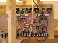
The railroad is protected by circuit breakers which automatically disconnect when there is a short and reconnect as soon as the short is removed. The railroad has four separate circuits, each with their own circuit breaker, so that a short in one area does not cause the whole railroad to come to a standstill. The railroad has one circuit for staging including the helix, one circuit for the Ascape yard where short circuits are more likely to occur, one circuit for the main line, and a fourth circuit for all the industrial sidings where shorts are also more likely to occur especially during switching moves. The circuit breakers were purchased from Rail Lynx.

Wiring with this system is very simple. A pair of 14 gauge buss wires follow the track. 18 gauge leads are soldered to the track about every 3 to 5 feet and connected to the buss wires with tap connectors. Each turnout is also connected to the buss wire. Having wired an earlier railroad using block control I can assure you that this type of wiring is very simple in comparison. Obviously the track is always hot and the control comes from the receiver in each locomotive (more on Rail Lynx later). For those who are interested, the Rail Lynx control system was reviewed in the July 2009 issue of Model Railroader magazine.

The return loop at the end of the yard requires that the polarity of the track be reversed when a train is in the loop. Our plan is to control this reverse polarity automatically with a Circuitron Auto Polarity Reverser (AR-1CC). At this writing it has not yet arrived. A later post will report on its operation.

Turnouts in the staging yard are controlled by Tortoise switch machines. Many thanks to Doug Whetstone and Craig Harding for laying on their backs all afternoon installing these machines. A railroad of this size would not possible without the help of many hands. These machines are wired for route control, that is, setting a rotary switch to a track number lines up all the turnouts for this track. The system used was described in the May 2009 issue of Model Railroader magazine (talk about good timing for an article). The first set of turnouts have all been wired and they work as expected, each turnout slowly moving to the correct setting when the rotary switch is moved to the track number.

The control panel for staging is under construction and will consist of a rotary switch for the ladder at each end of the staging yard. It will also contain a closed circuit TV to show the far end of the yard to the operator to facilitate operation when the scenery is in place above the yard. It will also control a signal at either end of the railroad so that the staging operator can indicate to operators whether or not they are clear to enter the helix to enter staging. More about this control panel in a later post.

Saturday, May 30, 2009

17 TIME OUT


Not much progress on the railroad during April and the first part of May. The president of the ATSG Railroad spend much of this time entertaining some cardiologists at Dixie Regional Medical Center. Unfortunately the procedures required some restrictions of activity and crawling around under a railroad was one of these restrictions. We are happy to report that the recovery is almost complete and the most recent visit to the physicians said no restrictions. However the chairman of the board still has a few restrictions being somewhat more conservative than the doctors.


So we are back and ready to move forward as seen in the next couple of posts.

Sunday, March 15, 2009

16 STAGING


Before proceeding with the roadbed at Ascape, it was thought the better part of wisdom to complete the staging yard underneath. Once again previous experience and the many scars on top of my head from installing staging under a complete railroad suggested that it is easier to reach through the open benchwork than to reach into a 10 inch shelf to install roadbed and track. By the way my wife bought me a hard had for working under the railroad. When I remember to wear it I don't get so many scars form whacking my head.

Staging is an important concept in model railroading. The best thing to do is think of a Model Railroad as a stage where action takes place for the viewing public. On a stage there is a back stage area where actors prepare to enter the stage and perform their role. A model railroad is similar. There is a staging area where trains are prepared to enter the visible part of the railroad to perform their role, moving across the railroad while delivering rolling stock to various industries, picking up or delivering passengers, etc. For the AT&SG this staging area is under the town of Ascape on the left side of the railroad. The staging area is about 10 inches below the ruling grade of the railroad. Trains enter the railroad by entering a helix at the left side of the staging yard or the bottom of the diagram shown here. (See the post on the helix for more details).

On the ATSG Railroad the staging yard serves both ends of the railroad via the helix. The trains enter at one level of the helix, travel across the railroad and return at another level of the helix to return to the staging area.

The operation of staging is as follows: trains enter at the left (bottom of the diagram) and travel though the ladder track to the short track on the near side (right side of the diagram). They then proceed around the reverse loop and enter an assigned yard track via the ladder at the right side (top of the diagram) where they await their next assignment.

Staging also allows a staging operator to use the reverse loop as a yard lead to switch the staging yard to rearrange trains for their next assignment or trains can merely wait for their next turn configured as they were when they entered staging. Trains leaving the staging yard can travel either direction across the railroad depending at which level they leave the helix.

The staging yard is suspended from the benchwork above as shown in the photos. The base is 3/8 plywood covered with homasote as a base for the track. The homasote we used is in 3 inch strips so these strips are staggered to accommodate the ladder tracks rather than covering all of the staging area.

The reverse loop at the end of the yard is constructed via spline roadbed as previously described. The spline in this case is suspended by supports from the benchwork above. One could never construct a railroad of this size without the help of friends. Craig Harding and Doug Whetstone deserve an award for duty exceeding all expectations as they labored several hours before they successfully got the suspended spline roadbed installed under the benchwork.

The other engineering challenge was to match the height of the roadbed to the homasote. The homasote is 1/2 inch thick, the cork on top of the spline is 3/16 inch so the spline had to be adjusted to come just above the height of the plywood base of staging to match the homasote.

At this posting the staging area is complete, the homasote in place, the cork installed on the reverse loop and in most of the helix and we are ready to begin laying track.

Saturday, February 14, 2009

15 SPLINE ROADBED


The Roadbed is the support under the track. The management chose to use spline for the roadbed for several reasons. First, it is much easier to bend the spine around curves than it is to cut plywood to the proper curvature. Second, spine tends to form a natural curve that provides natural transition curves.

A transition curve is one that gradually decreases the radius of the curve rather than a sudden change from straight to a curve of a given radius. This makes for much more pleasing curves that replicate curves on the prototype (real railroad) much more closely. However, the curves on a model railroad have a much smaller radius than the equivalent curve on the prototype because of the limited space.

So what is a spline? First we cut 1/4 inch Masonite into 1 inch strips. The first strip is placed on the joists or on risers to follow the plan for the track of the main line. This strip is held in place by screws placed temporarily on either side on each joist or riser.

After the first strip is in place the main line of the railroad is defined. The next step is to glue additional strips of Masonite to this guide strip. We mostly use hot glue to glue these splines together. The spline for this HO railroad required 8 splines to be glued together to form the roadbed that is 2 inches wide.

This process goes pretty fast but it does take a lot of strips and even more hot glue. If you have worked with hot glue you know that you have to work fast. We found that it is easier with a track crew (2 people), one to apply the glue and the other to immediately position and hold the spline in place. It is important to keep the top edges of the splines as level as possible during this gluing process.

The track crew found that when there is a turnout that the roadbed must accommodate this by allowing a spline to branch from the main spline. The crew found that gluing a small triangle to the first spline at the place of the turnout facilitated keeping the angle of the branching roadbed correct. The triangles were cut to accommodate the angle of the turnout. Most of the turnouts from the mainline on the Ascape Tennsion and Sulphur Gulch are #6 turnouts meaning that the branch line diverges 1 unit for every 6 unites of length. Again much more abrupt than the prototype but more practical for a model.

Where there are parallel tracks such as for a passing siding the crew found that it was more efficient to place a 1x2 between the splines as long as the parallel tracks were straight.

Once the splines have been glued it is critical that the top of the roadbed is level. We don't want the trains to lean from side to side as they proceed along the track. A very small difference in height on one side of the roadbed can made a noticeabledifference at the top of a railroad car as it moves over the track. It is inevitable that one or more splines slips up a fraction of an inch as it is glued in place. To level the roadbed the track crew found that a small belt sander was the tool of choice. The top of the roadbed is sanded until it is smooth and also to be sure that it is level.

With the spline roadbed in place it will be time to move to large flat areas where spline roadbed is not practical. This includes the staging area, the yard at Ascape, Park City, and Coalville. We are still working on the spline but come back soon for a description of the next phase.

14 THE TRESTLE AT SULPHUR GULCH


14 The Trestle at Sulphur Gulch


At last we get to see something that looks like a railroad rather than just lumber.

With the helix in place we needed to determine the location of the trestle at Sulphur Gulch. This trestle was constructed for the first version of the ATSG Railroad. It is based on a trestle that actually existed on the Southern Pacific Railroad many years ago. It is unique in that the trestle is on a grade (3%) and a curve. This was a challenge for the construction of the trestle. The trestle was constructed a number of years ago but perhaps a few details of its construction are of interest here.

The lumber was sawed from a single 1x4 piece of clear pine wood. Using a radial arm saw the 1x4 was first sliced into 1/4 inch strips. Using a miniture table saw these strips were then sawed into scale lumber of the various sizes needed for the trestle. Once the lumber was sawed the construction began.

The bents were constructed first by laying out the upright supports over the blueprint and held in place by double stick tape. The cross pieces were then glued in place for each bent. The glue was allowed to dry overnight and then the bent was turned over and the other side glued. This process was repeated for several weeks until all the bents had been constructed. A curve of plywood was then sawed to match the curve of the track where the trestle would be placed. This curve of plywood was then elevated to match the grade of the track. The track support on the top of the trestle were then placed on this curve under the location of the track and held in place with double stick tape. The bents were then glued to the track supports and held in a vertical position using a level. Then the cross pieces between the bents were glued in place. With the major construction completed the details were added such as ladders, a walkway, railings, etc.

This trestle has been stored for several years and has suffered some minor damage mostly to handrails and a few cross pieces but no structural damage.

Back to the present. It is necessary to have the trestle located before laying out the roadbed so that it is in the exact location necessary. The benchwork for the trestle is then build to accommodate its location. The operation has trains coming from staging into the helix and after a few turns exiting the helix onto the trestle. When the scenery is in place there will be a tunnel entrance just beyond the end of the trestle. The other end of the trestle leads to a track that has been blasted out of the side of a very steep cliff. This mountain and cliff will hide the helix when the scenery is in place.

So our challenge was to position the trestle to make sure it is lined up perfectly with the helix and then to build benchwork toaccommodate the roadbed leading to the other end of the trestle. Thisadditional benchwork was build around the benchwork that holds the helix as shown in the photos.

Once the benchwork was in place then the spline roadbed was lined up with the end of the trestle and supported on tall risers that will be hidden in the cliff that will go from above eye level (over 6 feet) to just above the floor. The track will then appear to have been blasted out of the cliff and then onto the trestle. You may not see this wonderful scenery in your mind's eye yet but check back in the near future and this scenery will appear.

If you have been following the progress on this reconstruction you may have noted that the location of Sulphur Gulch has moved from the peninsula in the middle of the room to in front of the helix. The chairperson of the board was very concerned that with narrow aisles for operators that a trestle on the back curve of the peninsula was sure to get damaged by giants in the land. Isn't it amazing that we can move a geological feature such as Sulphur Gulch to accommodate better viewing of this key feature of the AT&SG Railroad? Of course we will have to rewrite the history of the railroad to justify this move ... revisionsist history! The new location is much better, it provides a wonderful scene as visitors enter the railroad room and puts the key feature from which the railroad gets its name right up front. It is wise to listen to the chairperson of the board!

Tuesday, January 13, 2009

13 BENCHWORK


With the helix in place it was time to expand the benchwork. For those who may be new to model railroading the benchwork is the table that holds the model railroad. However in this case the management want flexibility for scenery. This means that we will use an open table consisting of support beams and open joists to which we will fasten the track and the scenery. With an open grid the scenery can extend below as well as above the top of the table. With a flat table top the scenery can only extend above the scenery.

The side of the benchwork against the wall is supported by TGI beams. These are beams that are usually used for floor joists. The advantage is that they are strong and can have a long span without supporting legs. We placed the TGI beams around the walls supported every 8 to 12 feet by a 2x4 leg that extends up past the TGI beam and thus supports the backdrop framework. (See post #7).

The front of our benchwork (table) is formed with an "L" beam. This is constructed of two 1x3s forming an L shape. The advantage is that the vertical board provides support and the horizontal board of the Lprovides a surface to which the joists can be screwed. The L beam is supported every 8 to 10 feet by a 2x2 leg. The L beam and legs were placed parallel to the TGI beams and vary in distance from the beams depending on the width of the railroad along the three walls.

Since the railroad room is a finished room with a hardwood floor which we covered with a non-glue vinyl floor covering (See post #4 ) it is very level, unlike some basement or garage floors. Therefore it was unnecessary to place levers on the bottom of the legs. To protect the floor there is a felt pad glued to the bottom of each leg.

The top of the benchwork consists of joists fastened to the TGI beam on one end and to the L beam. The joists overlap the L beam by several inches to enable the L beam and legs to be back from the edge of the layout. If the legs are at the edge of the layout there is a tendency to trip on the legs when running trains.

With the benchwork in place it is time to begin to lay the roadbed, the support for the railroad track.

Monday, January 12, 2009

12 THE HELIX


The first big (and we mean BIG) project was to construct a helix for the railroad.

If you are a model railroader you know what a helix is and its purpose. For the rest of you that may read this blog let's explain a bit.

The Ascape Tennsion & Sulphur Gulch Railroad is a bit like a stage play. There is the main stage where the action of the play takes place and then there are the wings or staging area where actors wait until it is their turn to appear on the scene and play their parts. Well a model railroad is similar. On the part of the railroad which the visitor sees, trains enter to deliver their freight cars to various industries and then leave the scene on their way to some distant unseen destination. A train enters at one location, travels across the visible part of the railroad, and then exits at the other end of the visible portion of the railroad.

Where do the trains come from and where do they go? Like a stage the model railroad has a staging area where the trains wait until it is their turn to enter the seen railroad and play their part, that is make their trip, deliver their goods or passengers, and then exit back to the staging area.

On the AT&SG the staging area is at a lower level under the town of Ascape. This staging area consists of a large rail yard where trains and rolling stock (freight cars and locomotives) can sit waiting for their turn to run on the railroad. On the far end of this staging area on the AT&SG there is a loop that can be used for turning trains. So when a train enters the staging area it goes around the loop and then into a siding in the yard ready for its next turn to enter the railroad.

On the other end of the staging yard is the helix. A helix is a spiral of track that allows trains to raise from the lower staging yard to the level of the main line of the railroad. The staging area of the AT&SG is about 10 inches below the main part of the railroad hidden under the scenery (or what will be scenery). When a train is ready to enter the railroad it enters the helix at one end of the yard travels around the spiral about 4 times until it is at a level where it can enter the main line of the railroad.

The journey across the AT&SG takes a train over the railroad on a lower level and then returns at a higher level back over the railroad. After completing its journey is enters the helix at a higher level and returns to the staging area having completed its work.

The remainder of this post is for those who are interested in how the helix was constructed. For the casual reader you may want to exit at this point.

Constructing the helix was an engineering challenge for the construction crew of the AT&SG. The challenge is a very smooth surface, a minimum grade sufficient to raise the trains to the appropriate level, and sufficient clearance between levels so that the trains have space to travel.

The construction crew decided to construct the helix from 3/8" plywood. Two complete circles of plywood 5 inches wide were cut from each of two 4x8 sheets of plywood. The outside diameter of each circle is 24 inches making the track radius 22 1/2 inches ( a rather tight radius, but since the AT&SG is circa 1937 most of the equipment is small with short 40 foot cars. There are a couple of 60 foot passenger cars but they can navigate these curves as well.) Using the remainder of the plywood 3 more circles were pieced together in sections.


The circles were then cut at one point to enable a spirial. The second section was attached to the first section using 1/4 in dowel pins with a piece of 1/8 Masonite glued to the underside to provide more stability at the joints. When all the joints were completed there was a spiral of 6 1/2 loops of continuous plywood ramp. This spiral of plywood loops was then secured to a framework base that raises the bottom of the helix to match the staging yard.

The next engineering challenge was how to support the spiral of plywood loops. The construction crew decided to use threaded rods and secure the loops with a nut and washer below and above each level. The original intent was to drill the holes in the plywood loops themselves but keeping the holes in line turned out to exceed the capabilities of the construction crew so an alternative method was devised. The posts were placed outside the plywood loops and a thin piece of fir (left over from ripping 2x4 studs for legs) were used under the plywood loops as shown in the illustration.

The tedious part was threading each of the 12 rods with 12 nuts and washers inserted between the supports. When the rods were all finally threaded with a nut and washer below and above each support the rods were secured into the platform framework to hold them securely in place.

The next step was to carefully raise each support to the correct level to promote a smooth upward spiral with a grade of 3% and a clearance between levels of 4 inches. When each support was at the correct level the nuts were secured both top and bottom of each support. When all was secured, the elevation checked, and the clearance checked then the plywood spirals were hot glued to the supports to provide stability.

When all was completed the helix was secure, stable, and ready for track and being connected to the track from staging and from the main line. It was critical to complete the helix before installing roadbed for either the staging yard of the main line. That is next. Check back for progress on this next phase of this project.

Sunday, January 4, 2009

11 SKY

 With the muslin pasted and dry we were ready to create the sky. Oh! Oh! Oh!
Creating a sky that looks like a sky is really a challenge. The sky painter finally adopted the approach recommended by Dave Frary in his How to Build Realistic Model Railroad Scenery. A similar technique is described and illustrated by Darryl Huffman in his videoEasy Backdrop Painting for Model Railroaders. The trick is to get the sky dark at the top and faded to a very light color at the bottom.

Benjiman Moore Utah Sky looked like a good color in the Ace Hardware paint store. However in reality it is way, way too dark and too intense. Experience suggests that subtle is better. So the sky painter mixed his own paint. He created four intensities of blue. The first mixed the Utah Sky blue with white at a ratio of 6 parts white to 1 part blue. This gave a good dark blue for the top of the sky. The second mixed 12:1, the third 24:1 and the bottom 50:1. This seemed to provide a pretty good transition. Next time (is there going to be a next time?) the second would be a bit whiter. Wow! Does a little blue paint go a long way. The illustration shows the four cans of paint.

We started at the top with a narrow band of our 6:1 blue. Using Darryl's technique we painted until our brush was dry and then dry brushed down into the second level with what was left on the brush. We applied the next intensity 12:1 and dry brushed it into the dry brush of the darker color and dry brushed into down into the next layer. Where the two colors mixed we scrubbed and scrubbed with the brush until there seemed to be a nice blend of the two colors. (Use cheap brushes, this destroys brushes.

The next layer used the same technique blending the 12:1 color with the 24:1 color and so forth with the bottom layer blending the 50:1 color with the 24:1 color. In most places, where brushed really scrubbed the paint the blending looks pretty good. In a couple of places the chairman of the board commented, "the sky painter must have been getting tired when this corner was painted!" The painter protested, "those are clouds." The chair person did not seemed convinced. Perhaps there will be a bit of touch up and the "clouds" eliminated.

With no benchwork and no scenery in place this is a lot of sky. About the lower half of the sky will be covered with scenery once the benchwork, track and scenery is in place. By itself there is a lot of light sky at the bottom but most of this will be covered. It was much easier to paint the sky with no benchwork in the way. Later the backdrop will be expanded with some mountains but this will have to wait until some scenery is in place.